MNS type Low Voltage Power Distribution Cabinet is suitable for power conversion, distribution and control of power distribution equipment in power plants, substations, petrochemical, metallurgical steel rolling, transportation and energy, light industrial textiles and other factories and mines, residential quarters, high-rise buildings and other places, as well as power systems with alternating current of 50-60Hz and rated working voltage of 660V or less.
Standards
MNS type Low Voltage Power Distribution Cabinet conforms to the national professional standards of GB7251.1 Low-voltage switchgear and JB/T9961 Low-voltage withdrawable switchgear, and the international professional standards such as IEC439-1.VDE0660 Part V.
Using Conditions
Ambient Temperature: -5 ~ 40 ºC, 24H average less than 35 ºC.
Atmospheric conditions: The air is clean, and the relative humidity should not exceed 50% at the highest temperature of +40ºC. At lower temperatures, higher relative humidity is allowed, for example, 90% at +20ºC, but temperature changes should be taken into account, and condensation may occasionally occur.
Altitude: Less than 1000m. MNS type Low Voltage Power Distribution Cabinet is suitable for transportation and storage at the following temperatures: -25ºC to +55ºC, and it can reach +70ºC within 24h in a short time. Under these extreme temperatures, the device should not be damaged irretrievably, and it should work normally.
If the above conditions cannot be met, it shall be settled through consultation between the user and the manufacturer.
When this device is used in offshore oil drilling and production platforms and nuclear power plants, a technical agreement shall be signed separately.
Electric Performance parameters of the MNS type Low Voltage Power Distribution Cabinet
Item
Data
Rated insulate voltage
660V(1000V)
Rated working voltage
380V,660V
Max working current of the main bus
5000A
Rated withstand current of the main bus
100KA/1s
Rated peak withstand current of the main bus
220KA/0.1s
Maximum working current of distribution bus
1000A
Peak current of distribution bus
Standard type
105KA(Max)/0.1s
Reinforced type
176KA(Max)/0.1s
IP degree
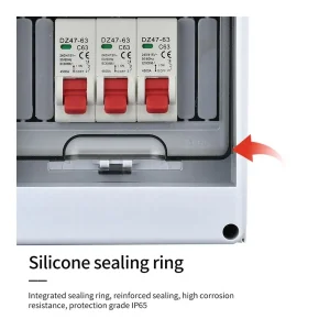
Comply with IEC529 and DIN40050 standards. IP30 protects solids larger than φ Φ2.5mm, IP40 protects solids larger than φ 41.0mm, and IP54 protects against dust and splashing in any direction (please consult with the manufacturer when ordering IP54 protection level).
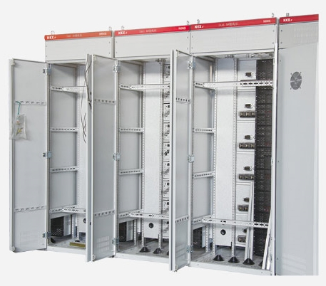
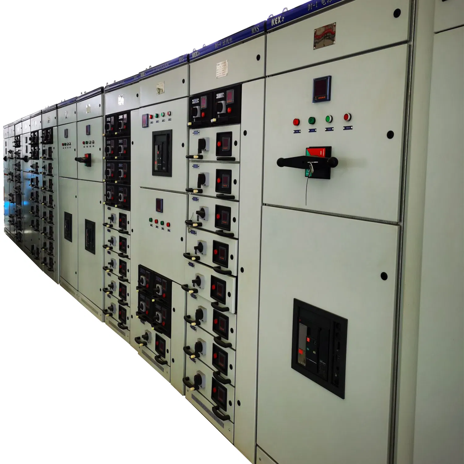
Cabinet structure
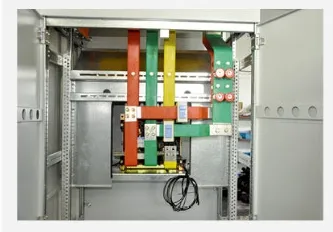
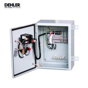
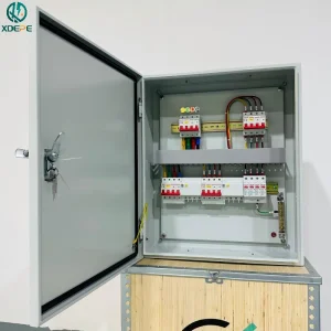
The basic structure of Low Voltage Power Distribution Cabinet is composed of C-shaped profiles. Section C is formed by bending steel plate with E=25mm as the module mounting hole. All cabinets and inner partitions are galvanized and purified. Around the door panels, side panels are made of high-voltage electrostatic spraying. See the figure below for the basic structure of the cabinet.
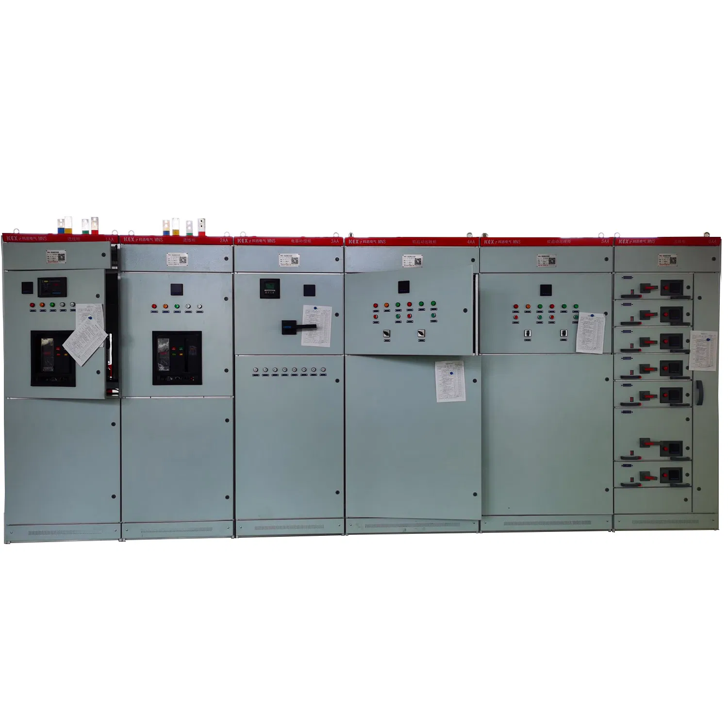
Switch cabinet type
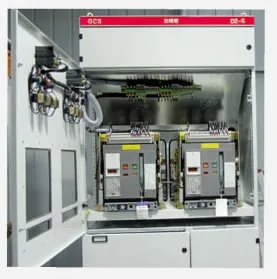
Distance between power distribution centers (PC1: Emax, MT, 3WN, AH, ME series circuit breakers can be used).
Motor control center cabinet (MCC): it is assembled by large and small drawers, and the main switch of each loop adopts high-breaking plastic case circuit breaker or rotary load switch with fuse. Automatic power factor compensation cabinet (with manual, automatic and remote power factor compensation devices).
A power distribution center (PC) cabinet parameters
Height (H)
Width (B)
Depth (T)
Depth (T1)
Depth (T2)
Note
2200
400
1000
800
200
Main bus transfer
2200
400
1000
800
200
F1s-1250-2000 ME630-1605
2200
600
1000
800
200
F2s-2500
2200
800
1000
800
200
F4s-3200 ME2000-3200
2200
1000
1000
800
200
F5s-4000 ME3205
2200
1200
1000
800
200
ME4005
B motor control center (MCC) cabinet parameters
Height (H)
Width (B)
Width (B1)
Width (B2)
Depth (T)
Depth (T1)
Depth (T2)
Note
2200
1000
600
400
600
400
200
1 side operation
2200
1000
600
400
1000
400
200
2 sides operation
Power distribution center (PC) compartmentalization details
The PC cabinet is divided into three compartments; Horizontal bus compartment: at the back of the cabinet; Functional unit compartment: on the front upper part of the cabinet or on the front left side of the cabinet.
Segmentation measures: The horizontal bus compartment and the functional unit compartment are separated by steel plates. The control loop compartment is separated from the functional unit compartment by a flame-retardant polyphenylene ether plastic cover.
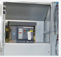
The frame circuit breaker installed in the cabinet can be manually operated outside the cabinet in the closed state. Observe the opening and closing state of the circuit breaker and judge whether the circuit breaker is in the test position or the working position according to the position relationship between the operating mechanism and the door.
A separation structure is designed between the main circuit and the auxiliary circuit. The auxiliary electrical units consisting of meters, signal lights and buttons are all installed on the plastic board, and the cover made of flame-retardant polyurethane foam plastic is separated from the main circuit behind the board.
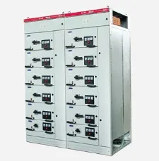
Pull-out motor control center and small current power distribution center (MCC)
The drawer-type MCC cabinet is divided into three compartments, namely, the horizontal bus compartment behind the cabinet, the functional unit compartment on the left in the front of the cabinet and the cable compartment on the right in the front of the cabinet. The horizontal bus compartment and the functional unit compartment are separated by functional boards made of flame-retardant foamed plastics, and the cable compartment is separated from the horizontal bus compartment and the functional unit compartment by steel plates. MCC motor control center drawers are divided into the following five types: 8E/4: height 200× width 150× depth 400 mm. 8E/2: height 200× width 300x depth 400 mm. 8E: height 200× width 600× depth 400 mm. 16E: height 400× width 600× depth 400 mm. 24E: height 600× width 600× depth 400 mm.
Rear outlet switch cabinet structure
In order to reduce the arrangement width of the switch cabinet, the main bus of the switch cabinet is horizontally installed at the top of the switch cabinet, and the rear half of the cabinet is a cable room, where incoming and outgoing cables are connected. The front of the switch cabinet is the device room, where the functional units of the switchgear are installed. In this system, the cable room on the side of the switch cabinet is moved to the rear cabinet, which greatly reduces the arrangement width of the switch cabinet to further meet the requirements of the space layout of the substation.
The feeder cabinet is 600mm wide and 1000/1200mm deep, with an independent main bus room at the top, which is isolated from the device room. The effective installation height of the front device chamber is 72E(E=25mm), which is separated from the rear cable chamber by the multifunctional board, making full use of the installation space of the switch cabinet, with compact structure and flexible unit configuration. The cable room on the back has a door, which is convenient for installation and maintenance. The width of the incoming cabinet is determined according to the frame current of the incoming unit. The recommended width is 400/600/800/1000mm, and the cabinet depth is 1000mm.
Drawer type Configuration
8E/4: Assemble 4 drawer units in 8E height space.
8E/2: Assemble 2 drawer units in 8E height space.
8E: Assemble a drawer unit in 8E height space.
16E: Assemble a drawer unit at a height of 16E(400mm).
24E: Assemble a drawer unit at a height of 24E(600mm). Five kinds of drawer units can be assembled singly in a cabinet, and can also be used for mixed assembly. See the table below for the maximum number of drawer units that can be accommodated in a cabinet for single assembly.
Drawer type
8E/4
8E/2
8E
16E
24E
Maximum units
36
18
9
4
3
Installation, use and maintenance
When the device arrives at the destination, first check whether the packing box is complete. If the device is not installed immediately, it should be stored in a dry and clean place.
The device is recommended to be installed away from the wall, or it can be installed against the wall. The installation foundation plane should be flat, and the horizontal error of foundation channel steel is 1/1000, and the total length deviation is 3 mm.
It is recommended to use Grade 8.8 and tension washer for the bolt fixing of all conductive parts, and the recommended tightening torque is shown in the table below:
Bolt specification
Tightening torque (N·m)
M6
9.5
M8
25
M10
45
M12
80
M16
200
Cable head sheath and a certain number of copper connectors for secondary circuit supplied by MCC scheme accessories. (In order to adapt to the cold pressing processing of copper joints, multi-core flexible wires are recommended for secondary cables).
After connecting the cable, the bottom of the device should be closed to prevent small animals from crawling into the cabinet and causing short circuit accidents.
After installation or adjustment, before putting into operation, the following inspections and tests are required:
Check whether the electrical equipment and control wiring installed in the device meet the requirements of the factory drawings.
Manual operation of various switches shall be flexible, without abnormality or jamming.
Check whether the actions of mechanical interlocking mechanism and electric interlocking device are correct and reliable, which should meet the system requirements.
Check whether the insulation resistance of the main circuit and the control circuit meets the specified requirements.
Check whether the electrical equipment installed in the device is in good contact and meets the technical requirements of the electrical appliance itself.
Check whether there is any foreign matter inside the device and whether the mounting screws of various parts are loose.
Operating instructions for pull-out MCC
Only after the bottom of the drawer enters the guide correctly can it be pushed into the cabinet, otherwise the drawer will be damaged or can't be pulled out.
The arrow from the breaking position "O" to the working position "I" in the figure indicates that the operating handle should be pushed in first and then rotated from "O" to "I". When returning, there is no need to push it, just turn the handle "I" to "O", and after letting go, the handle.
When the handle reaches the working position, the mechanism releases the mechanical lock on the main switch, and then the main switch can be closed and opened. However, when the main switch is closed, the handle of the interlocking mechanism cannot be operated. There is a small plastic cover on the door in the lower right corner that meets the sign, which is the unlocking mechanism of the door. The operation process is as follows: when the drawer is in the working position, if you want to open the door, first pull out the small cover, then insert the screwdriver into the hole and move the latch downward to open the door. Be sure to cover the small plastic cover after opening the door, otherwise the original protection level will be destroyed.
Transportation and storage of devices
The device is not allowed to tip over and suffer severe vibration. The transportation angle plate should be used when lifting the device after unpacking, and the included angle of two steel wires and ropes should be ≤120º. If a forklift truck, roller or crowbar is used, it is not allowed to be carried out directly on the underframe of the device.
When the device is installed in place, if you want to move the position for a short distance, you can pry it at the four corners of the chassis. Electrical products and parts are not allowed to be disassembled at will in the device. The rain should be prevented from getting wet, and the ambient temperature should be in accordance with the relevant provisions of this sample.
Completeness of products
The MNS type Low Voltage Power Distribution Cabinet is attached with packing list, product certificate, product instruction manual and necessary drawings, and the door key and spare parts provided according to the supporting list are attached.
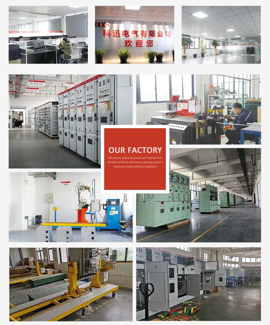
Company Profile
Packaging & Shipping
Frequently Asked Questions
Are you a trading company or a manufacturer?
We are a manufacturer, specializing in the sales of power transmission and transformation equipment of 35KV and below for decades.
How do you control the product quality?
We have QC department to follow TQM to ensure quality. If necessary, we can take photos or video confirmation for you.
Can products be customized with our own brand?
Of course, we accept OEM services to meet your brand specifications.
What are your main products?
Our main product range includes European box Substations, American box Substations, high pressure ring network cabinets, cable branch boxes, high-voltage complete series, low-voltage complete series, VCBs, disconnectors, and more.
What are your payment terms and MOQ?
We usually accept T/T and L/C payment methods. Our Minimum Order Quantity (MOQ) is 1 set.
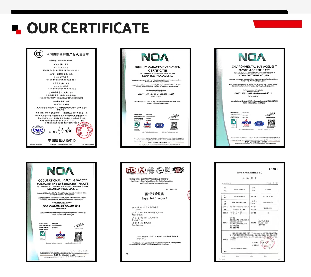
What certifications do you have?
We hold complete certifications including ISO9001, ISO14001, ISO45001, Type Test reports, and CQC certificates.