Sizing a power distribution box is not a guessing game. The right choice depends on connected loads, operating conditions, protection devices, and room for safe wiring. A box that looks large enough may still lack capacity for the actual circuit layout. A cramped enclosure can also make inspection and maintenance harder. Small details matter.
Electrical educator Mike Holt’s safety-focused guidance can be paraphrased this way: treat code requirements as a baseline, then verify the real installation. That principle is useful when learning how to size a power distribution box correctly. Start with an accurate load list, including continuous loads and equipment that may run at the same time. Check the supply voltage and phase. Then confirm the required bus, breaker, conductor, and enclosure ratings against the project specifications and manufacturer instructions. Never size from the outside dimensions alone.
There is no universal box size. A workshop panel, a commercial cabinet, and a machine enclosure can have very different needs. Ambient heat, cable entry points, spare capacity, and access for maintenance all affect the final selection. Some early estimates will need revision. That is normal, and worth catching before installation. The guide below covers ten practical checks, from calculating demand to reviewing clearances, so readers can make a sound preliminary choice and know when a qualified electrical professional should verify it.
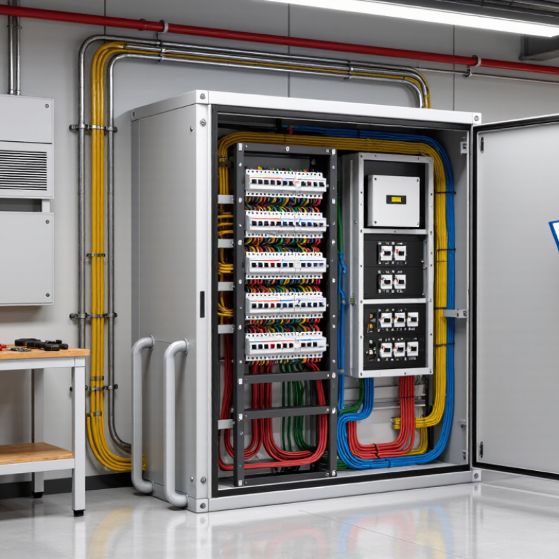
Define the Loads and Operating Conditions
Start with a load list, not the box dimensions. Record each device’s voltage, phase, rated current, and whether it runs continuously or intermittently. Include motors, heaters, lighting, controls, and spare circuits. Small details matter. A motor may draw several times its running current during startup, while a heater can remain at full load for long periods.
Then describe how the loads operate together. Note which equipment starts at the same time, how often it cycles, and whether production changes during a typical shift. Do not guess. A diversity assumption that looks reasonable on paper may fail when several machines restart after a brief outage. Check nameplate data against actual measurements where practical, and document any estimates that still need confirmation.
Operating conditions affect the choice, too. Record the highest expected ambient temperature, dust or moisture exposure, ventilation, and available mounting space. Heat can reduce the usable capacity of components, especially inside a crowded enclosure. Leave practical room for wiring and likely additions, but do not treat generous spare capacity as a substitute for accurate load data. Review the proposed demand and protective-device ratings with a qualified electrical professional; small changes in duty cycle or startup behavior can alter the result.
Top 10 Ways to Size a Power Distribution Box Correctly? - Define the Loads and Operating Conditions
Illustrative load schedule for a small commercial facility. Demand factors below are planning assumptions for this example, not universal code values; confirm actual equipment nameplates, applicable electrical codes, and site conditions before selecting equipment.
| Load / Assessment Item |
Quantity |
Unit Rating |
Connected Load |
Planning Demand Factor |
Estimated Demand |
Operating Conditions to Confirm |
| LED lighting |
40 fixtures |
0.02 kW |
0.80 kW |
1.00 |
0.80 kW |
Operating hours, emergency lighting, and any continuous-load requirements. |
| General-purpose receptacles |
20 outlets |
0.18 kW assumed |
3.60 kW |
0.50 |
1.80 kW |
Expected appliance use; replace the assumed outlet load with known equipment ratings where available. |
| HVAC units |
3 units |
2.50 kW |
7.50 kW |
1.00 |
7.50 kW |
Compressor starting current, seasonal operation, and whether units can run simultaneously. |
| Electric water heater |
1 unit |
4.50 kW |
4.50 kW |
1.00 |
4.50 kW |
Thermostat cycling, heating schedule, and local rules for fixed heating loads. |
| Water pumps |
2 pumps |
1.10 kW |
2.20 kW |
0.50 |
1.10 kW |
Assumes one duty pump operates at a time; include both if simultaneous operation or backup testing is required. |
| IT equipment |
2 racks |
1.20 kW |
2.40 kW |
0.80 |
1.92 kW |
Continuous operation, UPS losses, power-factor characteristics, and harmonic current. |
| Kitchen appliances |
1 group |
3.00 kW |
3.00 kW |
0.70 |
2.10 kW |
Which appliances may operate together and whether any have high inrush or heating loads. |
| Electric vehicle charger |
1 charger |
7.20 kW |
7.20 kW |
1.00 |
7.20 kW |
Charging schedule, continuous-load rules, and potential future addition of chargers. |
| Process equipment |
2 machines |
2.20 kW |
4.40 kW |
0.75 |
3.30 kW |
Production schedule, motor starting method, and whether both machines can run at once. |
| Ventilation fans |
2 fans |
0.75 kW |
1.50 kW |
0.80 |
1.20 kW |
Run time, interlocks with HVAC, and motor starting current. |
| Totals before design reserve |
37.10 kW |
— |
31.42 kW |
Estimated demand uses the stated planning factors. |
Illustrative sizing check: Adding a 20% planning reserve to the estimated demand gives approximately 37.70 kW. At an assumed 0.90 power factor, this is about 41.89 kVA. For a balanced 400 V, three-phase supply, the corresponding estimated line current is about 60.5 A. This estimate does not determine the final panel rating, protective-device size, conductor size, interrupting rating, or enclosure rating. Verify voltage, phase balance, ambient temperature, altitude, fault level, motor starting, continuous loads, and required spare capacity against the project design and applicable codes.
Calculate Demand and Account for Diversity
Top 10 Ways to Size a Power Distribution Box Correctly?
Calculate Demand and Account for Diversity
Add the nameplate loads, then separate equipment by how and when it operates. A kitchen’s ovens, refrigeration, and dishwasher rarely reach peak demand together. Treating every load as simultaneous can oversize the distribution box; assuming too much diversity can leave feeders overloaded. That balance matters.
The U.S. Energy Information Administration’s 2018 Commercial Buildings Energy Consumption Survey counted about 5.9 million commercial buildings across the country. Their different uses and operating schedules show why one blanket demand assumption is unreliable.
For a simple illustration, 12 loads rated at 2 kW each total 24 kW connected. If documented operating patterns support a 0.7 coincidence factor, estimated demand is 16.8 kW. That factor is only an example, not a default. Record the basis.
Use measured peak data where available, and check seasonal operation, future equipment, motor starting, and continuous loads. IEEE Std 3002.2-2018 provides guidance for calculating loads in industrial and commercial power systems; applicable electrical codes also set requirements. Keep assumptions visible and verify them against site conditions. Estimates can be imperfect. That is a reason to revisit them, not to hide them.
Choose the Voltage, Phase, and Distribution Layout
Choose a distribution box voltage that matches the incoming service and the connected equipment nameplates. A mismatch can prevent equipment from operating correctly or create avoidable hazards. Confirm the supply’s phase and frequency, too. Single-phase service may suit modest loads, while three-phase power often fits larger motors and multiple heavy loads. Check motor starting current, not only its running current. Small details matter.
The International Energy Agency’s Electricity 2024 report estimated that data centres, AI, and cryptocurrency used about 460 TWh worldwide in 2022; demand could exceed 1,000 TWh by 2026. That growth makes capacity planning more important, though this global figure cannot size an individual box.
Map the distribution layout around real loads: group circuits by area or function, balance loads across phases, and leave space for likely additions. Keep high-demand equipment on appropriately rated circuits. Avoid squeezing every breaker into the smallest enclosure. This step is often rushed. A useful review compares the load schedule with the one-line diagram, then checks enclosure space, bus rating, and future spare capacity. Have a qualified electrical professional verify the design against site conditions and applicable requirements.
Size the Busbars, Conductors, and Protective Devices
Correctly sizing a power distribution box starts with the actual load, not just the sum of equipment nameplates. Estimate demand, check continuous loads, and account for likely future additions. Then size conductors for the calculated current, installation method, ambient temperature, and grouping. Several warm cables in a tight duct can carry less current than an isolated cable. Heat adds up.
Busbars need similar care. Their material, cross-section, spacing, enclosure ventilation, and expected temperature rise all affect capacity. Don’t assume a larger-looking bar is automatically adequate. Verify its rating under the real enclosure conditions, and check that joints and supports can withstand expected fault forces. Leave room for airflow and maintenance. I’ve seen neat layouts become difficult to service once every spare gap gets filled.
Tips: Check the protective device against both the conductor’s allowable current and the load. Confirm its interrupting rating is suitable for the available fault current. Review coordination so a downstream fault is more likely to trip the nearest device. Recheck calculations when ambient conditions or the enclosure design changes. Small assumptions matter.
A final design review should compare drawings, equipment data, and field conditions. Use applicable electrical requirements and qualified engineering review for the installation. Document assumptions, especially where load estimates are uncertain. That uncertainty deserves another look.
Power Distribution Box Sizing: Load Current and Example Protection Ratings
Three-phase load current is calculated as I = S ÷ (√3 × V). This example assumes a 400 V system; the device ratings shown are illustrative candidates, not final selections.
Final protective-device, conductor, and busbar sizing must account for applicable codes, conductor ampacity and derating, installation conditions, fault current, temperature rise, and coordination.
Check Enclosure Space, Heat Dissipation, and Code Compliance
A power distribution box should fit the equipment and the wiring, not just the component list. Measure the usable interior after accounting for mounting rails, barriers, and door hardware. Leave room for conductor bends and terminals; a box that closes only when wires are forced into place is too small. Small details matter. Allow practical space for future circuits and safe inspection, while following equipment instructions for required clearances.
Heat needs an exit. Estimate the heat produced by the installed devices and consider the enclosure’s location, ambient temperature, and duty cycle. A box in a warm plant room may need more thermal allowance than one in a cool, open area. Do not assume a larger enclosure alone solves overheating. Check ventilation limits, enclosure ratings, and whether nearby equipment blocks airflow. If temperatures are uncertain, measure them under representative operating conditions.
Code compliance depends on the installation, not a generic sizing rule. Confirm applicable local requirements for working space, conductor fill, grounding, protection, and enclosure suitability. Requirements can vary by location and equipment type, so verify them against current rules and manufacturer documentation. A qualified electrical professional can review the layout before fabrication. It is easy to overlook a service tool’s reach or a cable entry that crowds a terminal, and those small oversights deserve another look.
Conclusion
Sizing a power distribution box correctly begins with a clear picture of every connected load and the conditions in which the system will operate. Identify normal and peak demand, startup currents, expected expansion, and the environment around the equipment. Then estimate the combined demand while allowing for diversity, since not all loads may operate at full capacity at the same time. This careful assessment helps prevent undersizing while avoiding unnecessary capacity.
Next, match the box to the required voltage, phase, and distribution layout. Select busbars, conductors, and protective devices to suit the calculated current and operating conditions, with appropriate safety margins. Finally, confirm that the enclosure has enough room for installation, wiring, and future maintenance, and that heat can dissipate effectively. Reviewing applicable codes and installation requirements completes the process. Together, these steps provide a practical guide to how to size a power distribution box correctly and support a reliable, safe, and maintainable electrical system.

 SN Electrical