How to Improve Power Distribution Box Performance?

Time:2026-09-22 Author:Isabella
0%

Improving a power distribution box begins with understanding what factors affect power distribution box performance. The answer is rarely limited to rated current. Heat, moisture, vibration, conductor size, connection quality, enclosure design, and load balance all shape daily operation. A box may pass a factory inspection yet perform poorly after months of dust, repeated switching, or uneven loading. That gap deserves attention.

John D. McDonald, an IEEE Fellow and recognized power-system specialist, has stated, “Reliability is designed into a power system; it is not added afterward.” This principle applies directly to distribution boxes. Engineers should verify voltage drop, short-circuit withstand capacity, busbar temperature, protective-device coordination, and grounding continuity. They should also inspect terminal torque and cable bending space. Small weaknesses can become hot spots. Heat leaves clues.

A practical improvement plan combines sound design with field evidence. Thermal imaging can reveal a warm lug before insulation darkens. Current measurements can expose phase imbalance during peak demand. Sealed cable entries can limit moisture, while corrosion-resistant materials support longer service in harsh areas. Scheduled cleaning and retightening also matter, although maintenance intervals must match the environment. Not always. A clean indoor panel needs less attention than a dusty outdoor enclosure.

Designers should follow applicable standards, including relevant IEC or UL requirements, and confirm every component’s certification. Still, compliance alone does not guarantee excellent performance. Installation quality, operating habits, and future expansion deserve equal review. Some recommendations may need revision after real measurements. That is not failure. It is responsible engineering. This article examines practical methods for improving efficiency, safety, thermal stability, and long-term reliability in modern power distribution boxes.
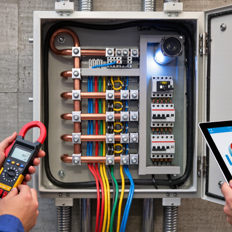
How to Improve Power Distribution Box Performance?

Understanding Power Distribution Box Components and Functions

How to Improve Power Distribution Box Performance? Understanding Power Distribution Box Components and Functions

A power distribution box is more than a metal enclosure. It controls, protects, and measures electrical energy before circuits reach equipment. Its main components include busbars, circuit breakers, fuses, terminal blocks, grounding conductors, surge protection devices, and monitoring meters. Busbars distribute current efficiently, while breakers interrupt abnormal loads. Fuses respond quickly to severe overcurrent conditions. Grounding paths reduce shock risk and help protective devices operate correctly.

According to the Uptime Institute’s 2023 Global Data Center Survey, 60% of respondents experienced an outage within the previous three years.

This finding shows why component coordination matters. Poorly selected breakers can trip too late, while undersized terminals may generate heat at connection points. The IEC 61439 standard also stresses verified assemblies, temperature rise limits, insulation, and short-circuit withstand capability. A box can look organized yet conceal loose lugs, unbalanced phases, or blocked ventilation. That is an uncomfortable weakness in many routine inspections.

Tips: Check torque values with calibrated tools, not guesswork. Record voltage, current, and temperature during normal operation. Inspect discolored insulation and hot terminals early. Keep spare protective devices matched to the approved design. Thermal scanning is useful, but it cannot replace visual inspection or functional testing. Field conditions often differ from drawings, and that difference deserves careful review.

Assessing Current Performance and Identifying Distribution Problems

A power distribution box should be assessed under real operating conditions, not only during a quiet inspection. Record incoming and outgoing voltage, phase current, frequency, and enclosure temperature. Compare these readings with the box’s rated capacity and recent maintenance records. A stable reading is encouraging, but it is not proof of good performance. Loads change throughout the day.

I once found a box that looked clean and properly labeled. However, one terminal was warmer than the others by nearly 18°C. A loose connection caused localized heating and intermittent voltage drops. Thermal imaging can reveal this hidden pattern quickly. Check for darkened insulation, melted plastic, unusual odors, cracked seals, and corrosion near cable entries. Listen for buzzing. Small clues matter.

Distribution problems often begin with uneven loading. Measure each phase during peak demand, then compare the results over several shifts. Repeated breaker trips may indicate overloads, poor coordination, damaged cables, or a failing protective device. Do not replace a breaker without finding the cause. That approach can hide the hazard. Inspect cable sizes, terminal torque, grounding continuity, and ventilation. Qualified personnel should isolate power before opening the enclosure. My early inspections focused too heavily on visible damage; trend records later proved more useful. A simple log of temperature, current, and trip events can expose problems before equipment stops unexpectedly.

Improving Electrical Safety, Capacity, and Load Management

How to Improve Power Distribution Box Performance?

Improving electrical safety, capacity, and load management requires more than installing larger breakers. A well-designed distribution box should separate lighting, motors, heating, and sensitive electronics. This prevents one overloaded circuit from affecting an entire workspace. The IEA Electricity 2024 report expects global electricity demand to grow by about 3.4% annually through 2026. Existing panels may face greater stress as equipment becomes more electrified.

Safety starts with inspection. Technicians should check loose terminals, heat discoloration, damaged insulation, and moisture entry. Infrared scanning can reveal hot connections before failure occurs. The Electrical Safety Foundation International reported 126 workplace electrical fatalities in 2020, based on U.S. Bureau of Labor Statistics data. That number is a warning, not just a statistic. Protective devices must match conductor ratings, fault levels, and local code requirements. A perfect load forecast is impossible. Good monitoring makes corrections earlier.

Tips: Record circuit loads during peak operation. Keep at least 20% spare capacity where practical. Label every outgoing circuit clearly. Test residual-current protection at scheduled intervals. Review temperature trends, not single readings. Do not assume a quiet panel is a healthy panel. In real facilities, unused circuits can hide poor connections or uneven phase loading. Periodic maintenance should follow applicable electrical standards and the equipment manufacturer’s instructions.

Optimizing Cooling, Enclosure Protection, and Internal Layout

How to Improve Power Distribution Box Performance?

Cooling, enclosure protection, and internal layout directly influence a power distribution box’s safety and service life. Heat has nowhere to hide. Field inspections often reveal blocked vents, tightly packed conductors, and undersized cooling paths. These conditions raise internal temperature and accelerate insulation aging. Calculate heat loads from breakers, terminals, and conversion devices before selecting fans or vents. Place warm components higher, where rising air can escape. Use filtered openings in dusty areas, but check their pressure drop regularly. Condensation also matters. In humid environments, controlled heaters or drainage features may prevent moisture from settling on terminals.

The enclosure should match the installation environment, not merely look robust. Confirm its ingress protection level against dust, water, oil mist, and washdown exposure. A damaged gasket can defeat an excellent enclosure design. Inspect door seals, cable glands, hinges, and fasteners during maintenance. For outdoor installations, consider ultraviolet exposure, corrosion, and temperature cycling. Pressure equalization may reduce stress on seals. Small details count.

Internal layout affects both cooling and maintenance. Keep high-current paths short, supported, and separated from sensitive control wiring. Maintain manufacturer-specified clearances around live parts and heat-producing devices. Leave enough space for a technician’s hand and test instrument. This step is easy to skip. Route cables neatly, but avoid sharp bends and excessive bundling. Use thermal scans after commissioning, then compare results under real load. The first layout may be acceptable, yet not ideal. Record hot spots, revise spacing, and verify terminal torque during follow-up inspections.

How to Improve Power Distribution Box Performance?

Cooling, enclosure protection, and internal layout influence the temperature rise inside a power distribution box. The chart shows representative internal temperature measurements during a 60-minute operation at constant electrical load.

Lower temperature rise improves component service life and helps maintain stable electrical performance. Forced airflow and clear separation between heat-generating components provide the strongest thermal improvement, while enclosure protection must be balanced with ventilation requirements.

Establishing Testing, Maintenance, and Performance Monitoring Procedures

How to Improve Power Distribution Box Performance?

Establishing Testing, Maintenance, and Performance Monitoring Procedures

A reliable power distribution box needs more than a successful installation. Establish a written testing procedure before energization. Qualified personnel should verify enclosure integrity, conductor identification, protective device settings, and grounding continuity. Insulation resistance testing can reveal damaged insulation that visual checks miss. Record test instruments, calibration dates, readings, and ambient conditions. Small details matter.

After commissioning, maintenance should follow both time and condition. Inspect cable terminations for discoloration, looseness, or cracked insulation. Use a thermal camera during representative loading, not only during idle periods. Compare temperatures with previous records. Clean ventilation paths and check door seals during scheduled outages. Replace damaged components under approved procedures and applicable electrical codes. Our early checklist looked complete, but it did not record load balance. That omission delayed diagnosis when one phase ran hotter than the others.

Performance monitoring should combine alarms, trend data, and physical inspections. Track current, voltage, power factor, temperature, fault events, and protective trips. Set practical thresholds, then review unusual changes before they become failures. A sudden rise in terminal temperature deserves investigation, even when production continues normally. Keep a clear action log with findings, responsible personnel, and verification dates. Review the procedure after every incident or near miss. Some readings may be wrong. Confirm them with a second instrument before making major decisions.

How to Improve Power Distribution Box Performance? - Establishing Testing, Maintenance, and Performance Monitoring Procedures
Performance Area Inspection or Test Item Recommended Frequency Measurement Method Typical Acceptance Criteria Alert or Action Threshold Corrective Action Record to Maintain
Enclosure Integrity Check enclosure, doors, hinges, locks, seals, cable glands, and unused openings Monthly visual inspection; after severe weather or modification Visual inspection and enclosure condition checklist No cracks, corrosion, loose hardware, water ingress, or blocked ventilation Any exposed live-part risk, damaged seal, or evidence of moisture Isolate equipment where necessary; replace seals or damaged parts; remove moisture source Inspection date, enclosure condition, defects, photographs, repair status
Connection Tightness Inspect busbar joints, terminal blocks, breakers, fuses, and grounding connections Annually; after fault events, vibration, or thermal abnormality De-energized visual inspection and calibrated torque tool Fasteners tightened to the equipment manufacturer’s specified torque Loose connection, discoloration, damaged conductor, or overheating marks De-energize, repair or replace the connection, and retest before return to service Torque value, tool calibration status, affected circuit, technician approval
Insulation Resistance Test conductors to ground and, where applicable, between isolated conductors During commissioning; periodically according to site risk assessment Insulation resistance tester at the voltage specified by the applicable procedure Meets the applicable installation standard and the equipment manufacturer’s limit Significant decline from the established baseline or an unacceptable measured value Investigate contamination, moisture, damaged insulation, and connected loads before retesting Test voltage, measured resistance, ambient conditions, circuit identification
Protective Devices Verify breaker, fuse, residual-current, and overload protection settings and condition Semi-annually; after trip events or circuit changes Visual verification, settings review, and functional or secondary-injection test where required Settings match the approved coordination study and device documentation Unexpected trip, bypassed protection, incorrect rating, or inaccessible reset mechanism Determine fault cause; restore approved settings; replace defective protective device Device identification, settings, trip history, test results, approval reference
Thermal Condition Scan busbar joints, terminals, breakers, cable entries, and high-load circuits Quarterly under representative load; after overload or repeated trips Infrared thermography by a qualified person with comparable load conditions No abnormal hot spot; phase-to-phase temperature differences remain low and explainable Temperature differential of approximately 10°C or more between comparable connections requires investigation Check load balance and torque; repair, clean, or replace the affected component Thermal image, load current, ambient temperature, hotspot location, action taken
Voltage Quality Monitor phase voltage, undervoltage, overvoltage, transients, and interruptions Continuous monitoring; review weekly and after supply disturbances Power-quality meter or approved monitoring system Voltage remains within the permitted operating range for connected equipment Repeated excursions outside the equipment’s rated voltage range or unexplained interruptions Check upstream supply, neutral connections, loading, and surge-protection condition Time-stamped voltage trends, event duration, affected circuits, investigation result
Load Balance Compare phase currents and identify overloaded or lightly loaded circuits Monthly; continuously where monitoring is installed Clamp meter, multifunction meter, or fixed energy monitor Continuous current remains below the conductor and protective-device rating Any phase exceeds 80% of its continuous rating for the planned operating period Redistribute single-phase loads, remove nonessential loads, or upgrade capacity after engineering review Phase current, demand trend, circuit utilization, peak time, balancing action
Power Factor and Harmonics Review power factor, total harmonic distortion, and nonlinear-load impact Monthly trend review; detailed assessment when symptoms occur Power-quality analyzer or permanently installed meter Values remain compatible with the utility agreement, equipment ratings, and system design Persistent low power factor, capacitor overheating, nuisance trips, or elevated harmonic distortion Assess filtering, compensation, neutral loading, and compatibility before making modifications Power factor trend, harmonic spectrum, load profile, equipment symptoms, engineering decision
Grounding and Bonding Inspect protective conductor, bonding jumpers, grounding bar, and continuity Annually; after modification, fault, or enclosure replacement Continuity tester and applicable grounding-system test method Low-resistance, secure, corrosion-free bonding path with correct conductor identification Open circuit, loose bonding strap, corrosion, or resistance outside the approved limit Repair bonding path and repeat continuity testing before energization Test points, measured resistance, conductor size, defects, verification signature
Ventilation and Environment Check ambient temperature, humidity, dust, airflow, and clearance around the box Monthly; continuous monitoring in critical or harsh environments Environmental sensor and visual inspection Conditions remain within the enclosure and component operating limits Blocked airflow, condensation, excessive dust, or temperature above the equipment rating Improve ventilation, clean safely, control condensation, or relocate heat sources Temperature, humidity, cleaning status, clearance measurement, environmental alarms
Functional Operation Verify indicators, meters, controls, interlocks, emergency isolation, and labeling Quarterly; after maintenance or control changes Operational test under an approved safe-work procedure Controls operate correctly, labels are legible, and isolation functions as intended Failed indication, unclear circuit identification, defective interlock, or inaccessible isolation Repair control circuit, update labels, and verify safe isolation before normal operation Functional test checklist, failure description, repair reference, retest result
Performance Reporting Review availability, unplanned trips, alarm count, energy use, defects, and overdue actions Monthly management review; quarterly trend analysis Maintenance management system and power-monitoring dashboard All critical inspections completed on schedule and corrective actions closed by due date Repeated trips, rising thermal alarms, overdue safety actions, or declining availability Perform root-cause analysis, revise the maintenance plan, and allocate corrective resources Monthly KPI report, action log, trend charts, root-cause analysis, management review
Safety and compliance note: Testing and maintenance should be performed only by qualified personnel under an approved electrical safety procedure. Apply isolation, lockout/tagout, verification of absence of voltage, and the applicable local electrical codes before working inside the power distribution box.

FAQS

What are the main components inside a power distribution box?

Common components include busbars, circuit breakers, fuses, terminal blocks, grounding conductors, surge protection, and meters. Busbars carry current efficiently. Breakers interrupt abnormal loads. Fuses react quickly to serious overcurrent conditions. Grounding paths support safer fault clearing.

Why does component coordination matter?

Poor coordination can delay protective action or cause unnecessary trips. An undersized terminal may become hot at its connection point. Unbalanced phases can overload one section quietly. A neat enclosure can still hide serious weaknesses.

How can heat buildup be reduced?

Calculate heat from breakers, terminals, and conversion devices before choosing cooling methods. Place warmer components higher inside the enclosure. Keep vents clear and use filters in dusty areas. Heat has nowhere to hide. Check filter pressure loss regularly.

What enclosure details require regular inspection?

Check the enclosure’s protection level against dust, water, oil mist, and washdown exposure. Inspect gaskets, cable glands, hinges, and fasteners. A damaged gasket can defeat strong enclosure protection. Outdoor boxes also need attention to sunlight, corrosion, and temperature changes.

How should components and cables be arranged internally?

Keep high-current paths short, supported, and separated from sensitive control wiring. Maintain required clearances around live and hot components. Leave enough room for a technician’s hand and test instrument. Avoid sharp cable bends and excessive bundling. The first layout may be acceptable, not ideal.

What tests should be completed before energization?

Qualified personnel should verify enclosure condition, conductor identification, protective settings, and grounding continuity. Insulation resistance testing can reveal hidden insulation damage. Record readings, instrument details, calibration dates, and ambient conditions. Small details matter.

What should routine maintenance include?

Inspect terminations for discoloration, looseness, and cracked insulation. Use thermal scanning during representative loading, not only at idle. Clean ventilation paths and inspect door seals during scheduled outages. Check torque with calibrated tools. Guesswork is risky.

Which operating data should be monitored?

Track current, voltage, power factor, temperature, fault events, and protective trips. Compare new readings with earlier records. A sudden terminal temperature rise deserves investigation. Some readings may be wrong. Confirm unusual results with another instrument. Record actions and verification dates.

Conclusion

Improving power distribution box performance begins with understanding how components such as circuit breakers, busbars, terminals, protective devices, and monitoring equipment work together to distribute electrical power safely and efficiently. A careful assessment of current operation can reveal voltage drops, overloads, uneven phase loading, loose connections, overheating, and other distribution problems. Asking “what factors affect power distribution box performance” helps guide a structured review of load demand, component condition, ambient temperature, enclosure protection, wiring quality, and maintenance practices.

Performance can be strengthened by selecting suitable capacity, balancing loads, improving protection settings, and maintaining clear separation between power and control wiring. Effective cooling, appropriate enclosure sealing, organized internal layouts, and secure cable routing can further reduce heat buildup and operational risks. Finally, scheduled inspections, electrical testing, thermal checks, connection tightening, and performance monitoring should be established to detect deterioration early. These procedures support reliable operation, extend equipment service life, and help ensure that the distribution box continues to meet changing electrical demands safely.

Isabella

Isabella

Isabella is a dedicated marketing professional with a sharp focus on driving brand growth and engagement through strategic content creation. With an extensive background in digital marketing, she combines her passion for storytelling with her keen understanding of industry trends to deliver......